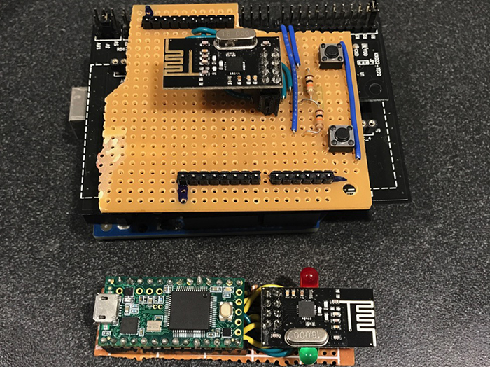
在利用ROHM传感器评估套件实现UCLA AirMouse – 第1部分中,我们完成了项目的硬件。对于发射器部分,我们将AirMouse按钮以及Uno的GPIO引脚和RF模块之间的接口组装在一块面包板上。由于ROHM传感器开发板(SensorShield)在原型设计和DIY项目方面的应用非常方便,因此我们选择将其与加速度计模块接合在一起使用。正如您将在本教程中看到的那样,ROHM开发板内置Arduino与其外设之间的I2C通信功能,因此,用户通过一些简单代码就可以接收加速度计的数据,无需编写任何底层I2C函数来发送和接收来自设备地址的数据。对于接收器部分,我们为Teensy微控制器组装了类似的分线板,以便与RF模块对接。
本教程介绍和描述的代码将帮您将两个模块连接在一起,以完成该项目。我们将向您展示两个模块之间发送数据的基本代码以及处理加速度计数据以在计算机显示器上移动光标的基本代码。同时,我们希望您能创造一些更酷的补充和改进!
AirMouse快速概览
我们都用过电脑鼠标,但是它们只能在桌面之类的平面上工作。我们已经制作了一个“AirMouse”——一款能够在3D空间中运行的计算机鼠标。用户通过倾斜鼠标就可以让屏幕上的光标移动,从而可以进行大范围自定义动作。我们已经在第1部分中介绍了构建AirMouse的基础知识。AirMouse主要由两部分组成:戴在手上的鼠标发射器和连接用户计算机的接收器。发射器收集鼠标的方向和按钮状态信息;而接收器则负责转换这些信息,从而在计算机屏幕上执行相应操作。AirMouse由Arduino Uno和nRF24L01射频模块结合ROHM传感器开发板的加速度计构建而成。
第1部分的硬件:
发射器:
- ● 1 x Arduino Uno微控制器
- 1 x ROHM传感器评估套件
- 1 x ROHM加速度计 (KX022-1020)
- 1 x nRF24L01+ RF模块
- 排母
- 滑动开关
- 1 x 可焊接试验电路板,足够大,能焊接微控制器和所有电子器件
- 2 x 按键
- 1 x 1s LiPo电池
- 1 x 1kΩ电阻r
- 1 x 3.3kΩ电阻
接收器:
- 1 x Teensy 3.2微控制器
- 1 x NRF24L01+ RF模块
- 排母
- 1 x 可焊接试验电路板,足够大,能焊接微控制器和所有电子器件
- 1 x 红、黄、绿LED灯
- 1 x 150Ω电阻
按照第1部分连接硬件之后,您就可以利用以下程序运行发送器和接收器。
发射器:
#include <SPI.h>
#include "RF24.h"

#define byte uint8_t
#include <Wire.h>
#include <KX022.h>

KX022 accelerometer(KX022_DEVICE_ADDRESS_1E);

RF24 radio(9,10);

uint64_t pipes[2] = {0xF0F0F0F0F0, 0xF0F1F1F1F1}; //reading, writing

void initRadio()
{
 radio.setPALevel(RF24_PA_HIGH);
 //payload size default 32...
 radio.setChannel(10); //you can change the channel setting
 radio.setCRCLength(RF24_CRC_16); //2-byte CRC
 radio.setDataRate(RF24_1MBPS); //1Mbps data rate

 radio.openReadingPipe(0, pipes[0]);
 radio.openWritingPipe(pipes[1]);
}

#define buttonPinR 2 //change these accordingly
#define buttonPinL 3

void setup() {
 // put your setup code here, to run once:
 Serial.begin(9600);
 while (!Serial);

 pinMode(buttonPinR, INPUT);
 pinMode(buttonPinL, INPUT);

 radio.begin();
 initRadio();
 radio.stopListening();

 Wire.begin();
 accelerometer.init();
}

long lastDebounceTimeR = 0;  // the last time the output pin was toggled
long lastDebounceTimeL = 0;
long debounceDelay = 50;
int buttonStateR = LOW;             // the current reading from the input pin
int buttonStateL = LOW;
int lastReadingR = LOW;
int lastReadingL = LOW;

char readButtonR(){
 int reading = digitalRead(buttonPinR);//get what state the button is
 char out = 'a';//the value to return if nothing special happened

 if (reading != lastReadingR) {//We're reading a new state for button
   // reset the debouncing timer
   lastDebounceTimeR = millis();
 }

 if ((millis() - lastDebounceTimeR) > debounceDelay) {//We finally have a stable value
   if (reading != buttonStateR)//Compared to our previous state, we have a flip
   {
     out = 'r';//prepare to toggle the Mini
   }
   buttonStateR = reading;//Make the buttonState the same
 }

 lastReadingR = reading;//make the last state the "current" state
 return out;
}

char readButtonL(){
 int reading = digitalRead(buttonPinL);
 char out = 'a';

 if (reading != lastReadingL) {
   // reset the debouncing timer
   lastDebounceTimeL = millis();
 }

 if ((millis() - lastDebounceTimeL) > debounceDelay) {

   if (reading != buttonStateL)
   {
     out = 'l';
   }
   buttonStateL = reading;
 }

 lastReadingL = reading;
 return out;
}

struct data
{
 boolean isPushedR = false;
 boolean isPushedL = false;
 int8_t acceleration[3] = {0, 0, 0};
};

data packet;
boolean rState = false;//these states are used to represent the current state of the buttons
boolean lState = false;

void loop() {

   if(readButtonR() == 'r'){ //toggle button state when button state change is detected
     rState = !rState;
   }

   if(readButtonL() == 'l'){ //toggle button state when button state change is detected
     lState=!lState;
   }

   packet.isPushedR = rState;
   packet.isPushedL = lState;

   uint8_t rc;
   float acc[3];
   rc = accelerometer.get_val(acc);

   if (rc == 0)
   {
     //we cast to drop the decimal, we don't need that high precision
     packet.acceleration[0] = (int8_t)(acc[0]*100); //x
     //Serial.print(packet.acceleration[0]); Serial.print(" ");
     packet.acceleration[1] = (int8_t)(acc[1]*100); //y
     //Serial.print(packet.acceleration[1]); Serial.print(" ");
     packet.acceleration[2] = (int8_t)(acc[2]*100); //z
     //Serial.println(packet.acceleration[2]);
   }

   radio.write((char*) &packet, sizeof(packet));
}
接收器:
#include <SPI.h>
#include "RF24.h"

RF24 radio(9,10);

uint64_t pipes[2] = {0xF0F1F1F1F1, 0xF0F0F0F0F0}; //reading, writing

void initRadio()
{
 radio.setPALevel(RF24_PA_HIGH);
 //payload size default 32...
 radio.setChannel(10);
 radio.setCRCLength(RF24_CRC_16); //2-byte CRC
 radio.setDataRate(RF24_1MBPS); //1Mbps data rate

 radio.openReadingPipe(0, pipes[0]); //reading pipe
 radio.openWritingPipe(pipes[1]);

 radio.startListening();

}
#define R_PIN 6 //Red LED
#define G_PIN 7 //Green LED
#define Y_PIN 8 //Yellow LED

void setup() {
 Serial.begin(9600);
 while(!Serial); //wait until Serial is initialized...(we found that not including this line of code caused errors on the
                 //Teensy because it started executing code without ensuring that Serial communication with the laptop was
                 //properly initialized...
 radio.begin();
 initRadio();

 Mouse.screenSize(1920, 1080);  // configure screen size

 randomSeed(analogRead(0));

 pinMode(R_PIN, OUTPUT);
 pinMode(G_PIN, OUTPUT);
 pinMode(Y_PIN, OUTPUT);
}

#define CALIX 6 //calibration for X
#define CALIY -1 //calibration for Y

#define scalingFactor 0.05
#define THRESHOLD 1

double moveVector[2] = {0, 0};

void tiltToVector(const int8_t* acceleration){
 moveVector[0] = 0;
 moveVector[1] = 0;
 if(abs(acceleration[0] - CALIX) > THRESHOLD){ //calculate move
   moveVector[1] = (double)(acceleration[0] * scalingFactor);
 }
 if(abs(acceleration[1] - CALIY) > THRESHOLD) {
   moveVector[0] = (double)(acceleration[1] * scalingFactor);
 }
}

struct data
{
 boolean isPushedR = false;
 boolean isPushedL = false;
 int8_t acceleration[3] = {0, 0, 0};
};

data packet;

void loop() {

 bool stillWaiting = true;
 //Serial.println("About to read");
   while(stillWaiting){
     if(radio.available(0)){ //You've got mail!!!
       radio.read((char*) &packet, sizeof(packet));
       stillWaiting = false;
     }
   }

 Mouse.move(moveVector[0], moveVector[1]);
 Mouse.move(moveVector[0], moveVector[1]); //call it twice within the loop for smoothness :)

 //prints for debugging purposes
 Serial.println("Finished writing the pins");
 if (packet.isPushedR) {
   Serial.println("The right button has been clicked!!! (Did you mean to right click?!?!)");
 }

 if (packet.isPushedL) {
   Serial.println("The left button has been clicked!!! (Did you mean to left click?!?!)");
   //Mouse.click();
 }

 Serial.print("X: ");
 Serial.println(packet.acceleration[0]);

 Serial.print("Y: ");
 Serial.println(packet.acceleration[1]);

 Serial.print("Z: ");
 Serial.println(packet.acceleration[2]);

 tiltToVector(packet.acceleration); //re-calculate move vector coordinates


//  Mouse.move(moveVector[0], moveVector[1]);

}
将代码上传到Teensy与将代码上传到Arduino Uno略有不同。对于Uno,您只需按照通常的编译和上传步骤执行即可:
- 依次选择Tools > Board > Arduino/Genuino Uno
- 选择端口(Port)
- 点击Arduino IDE中的“Upload”(上传)按钮
而对于Teensy,请按照以下步骤上传接收器代码:
- 依次选择Tools > Board > Teensy 3.2 / 3.1
- 依次选择Tools > USB Type > Keyboard + Mouse + Joystick (我们将Teensy当作一个USB设备使用)
- 点击Arduino IDE中的“Upload”(上传)按钮
为了本教程的目的,我们不会详细涉及所使用的不同通信协议,也不会详细介绍RF模块的通信软件。要了解有关这些主题的更多信息,请查看我们的 通信协议 和 nRF24L01+ 模块 教程 相反,我们将简要介绍软件中主控制电路的工作原理。
在AirMouse中,发射器负责收集数据,但大部分数据处理由接收器模块进行。系统的这种设计方式使得Arduino——比Teensy更弱的处理器——只需要收集数据即可,因此能够在决策和计算上花费更少的资源,并能够以更快的周期运行。通过这种实现方法,两台设备之间唯一发送的数据就是原始加速计数据和按钮数据。Teensy接收这些原始数据并进行处理,从而在计算机屏幕上执行相应操作。
为了检测AirMouse的方位,系统必须能够解析原始加速计数据。要做到这一点,首先必须确定每个坐标的“零值”。零值的定义如下:AirMouse保持平坦(平行于地面)时每个轴的加速度计输出。确定零值后,软件就能够将加速度计数据转换为方向和数量,通过分析每个轴的加速度(由于重力)并将其与零值进行比较以便在屏幕上移动光标。
现在,我们来看一下接收器模块与电脑之间的交互。Teensy被指定为USB人机界面设备(这里是指USB鼠标)。解析方位数据后,软件会计算光标移动的速度和方向。此外,该软件还将点击左键解析为左键单击,将点击右键解析为右键单击,调用适当的方法在计算机屏幕上显示左键单击或右键单击功能。以下才是最酷的部分:您完全可以只通过软件就能够修改或添加鼠标的屏幕功能!目前,鼠标只具有最基本的功能和特性,但是您只需对软件进行简单改动,就可以轻松添加诸如滚动、将光标移至屏幕上的某个点等功能!(请点击此处,了解Teensy USB鼠标的参考指南) 以下是您可以实现的一些很酷的硬件和软件想法:
- 将不同模式的按键点击用作不同的控制功能(比如,双击右键关闭窗口)
- 添加滚动功能!(同时点击两个按键变为“滚动模式”)
- 添加其他鼠标按键以执行滚动操作或为不同功能获取更多按键模式
我们希望您能够喜欢这个AirMouse项目,并且非常期待您可以对设计和功能进行修改和改进!
作为UCLA IEEE高级项目(Advanced Projects)计划的一部分,最初的AirMouse由Rahul Iyer、Aaron和Andrew Wilhelm研发。更多信息请参阅 https://ieeebruins.org
Device Plus正在寻找与活跃的学生工程组织和实验室展开合作。想了解我们硬件赞助计划的更多信息,请通过以下电子邮件联系我们:info@deviceplus.com

Rahul Iyer
Rahul是加州大学洛杉矶分校电气工程学院的学生,爱好电子和机器人项目,尤其热衷于电动汽车技术和辅助机器人技术。