这篇文章来源于DevicePlus.com英语网站的翻译稿。
在第1部分中,我们能够获取KX022-1020加速度计的数值并将其显示到TFT液晶LCD面板上。在第2部分中,我们将展示如何在读取程序内容的同时控制TFT显示屏!
今天的电子食谱
预计完成时间:60分钟
所需部件:
- Arduino 主体 (Arduino UNO R3)
- 罗姆传感器评估套件https://www.rohm.com/web/global/sensor-shield-support
- TFT 液晶面板 (sainsmart 1.8) https://www.sainsmart.com/sainsmart-1-8-spi-lcd-module-with-microsd-led-backlight-for-arduino-mega-atmel-atmega.html
※ 您可以从以下站点购买罗姆传感器评估套件!
通过Arduino在TFT液晶显示屏上显示数据
和之前一样,我们使用SainSmart ST7735RTFT显示屏。这是一款紧凑的LCD显示屏,可兼容Arduino和Raspberry Pi。该显示屏具有内置microSD卡插槽,因此除了读取和写入数据外,还可以存储和加载图像。在本教程中,我们将仅尝试在该TFT显示屏上显示数值。
我们开始吧!首先,将TFT显示屏与Arduino连接起来。
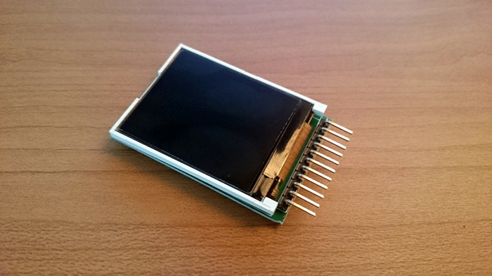
图1 SainSmart ST7735R TFT显示屏
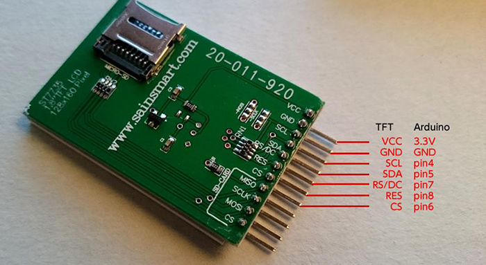
图2 TFT显示屏的背面
TFT 引脚定义:
- VCC – 供电电压
- GND – 地
- SCL – 串行时钟线
- SDA – 串行数据线
- RS / DC – 命令/数据选择
- RES – 控制器复位
- CS – TF卡的片选信号
将Arduino连至TFT显示屏之后,我们来运行示例程序。
将TFT显示屏库文件应用于Arduino
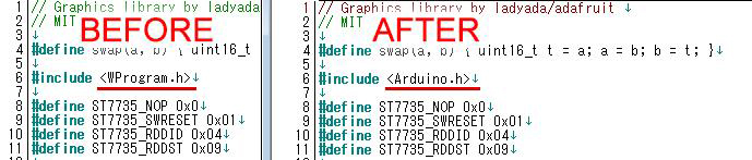
正如文章第1部分中提到的,我们需要对库文件(ST7735R)进行一些小的修改,以便让TFT显示屏兼容Arduino系统。
用于Arduino的SainSmart 1.8 ST7735R TFT液晶显示屏,搭载MicroSD卡槽和LED背光
Raspberry Pi 库 (ST7735R V0.2)
上述URL的页面底部有一个下载链接。单击页面上标有 “Download Link” 的链接,下载完整的库、示例代码及文档等。下载完成后,解压文件并重新编写必要的文件。
请用能够编辑文本的编辑器打开 “ST7735.h” ,然后更改下图所示的部分。您也可以使用Arduino IDE。
更改完成后,用zip再次压缩 “TFT 18” 目录,然后在Arduino(或Arduino Create)Add Library中将其作为一个库添加;或者将其放置在Arduino安装目录的“libraries”目录下并加载该库。
导入库之后,请尝试在示例程序中移动 “TFT 18” – “graphictest” 。
您会看到示例程序的显示非常流畅。
示例程序 – graphictest
//Pin setting
#define sclk 4
#define mosi 5
#define cs 6
#define dc 7
#define rst 8
//Color numbering
#define BLACK       	0x0000
#define BLUE        	0x001F
#define RED         	0xF800
#define GREEN       	0x07E0
#define CYAN        	0x07FF
#define MAGENTA     	0xF81F
#define YELLOW      	0xFFE0
#define WHITE       	0xFFFF
#include <ST7735.h>
#include <SPI.h>
ST7735 tft = ST7735(cs, dc, mosi, sclk, rst);
void fillpixelbypixel(uint16_t color) {
 for (uint8_t x=0; x < tft.width; x++) {
   for (uint8_t y=0; y < tft.height; y++) {
     tft.drawPixel(x, y, color);
   }
 }
 delay(100);
}
void setup(void) {
 Serial.begin(9600);
 Serial.print("hello!");
 tft.initR();           	// initialize a ST7735R chip
 Serial.println("init");
 tft.writecommand(ST7735_DISPON);

 uint16_t time = millis();
 tft.fillScreen(BLACK);
 time = millis() - time;

 Serial.println(time, DEC);
 delay(500);

 //
 tft.fillScreen(BLACK);
 testdrawtext("Lorem ipsum dolor sit amet, consectetur adipiscing elit. Curabitur adipiscing ante sed nibh tincidunt feugiat. Maecenas enim massa, fringilla sed malesuada et, malesuada sit amet turpis. Sed porttitor neque ut ante pretium vitae malesuada nunc bibendum. Nullam aliquet ultrices massa eu hendrerit. Ut sed nisi lorem. In vestibulum purus a tortor imperdiet posuere. ", WHITE);
 delay(1000);

 //a single pixel
 tft.drawPixel(tft.width/2, tft.height/2, GREEN);
 delay(500);

 // line draw test
 testlines(YELLOW);
 delay(500);

 // optimized lines
 testfastlines(RED, BLUE);
 delay(500);
 testdrawrects(GREEN);
 delay(500);
 testfillrects(YELLOW, MAGENTA);
 delay(500);
 tft.fillScreen(BLACK);
 testfillcircles(10, BLUE);
 testdrawcircles(10, WHITE);

 Serial.println("done");
 delay(1000);
}
void loop() {
 tft.writecommand(ST7735_INVON);
 delay(500);
 tft.writecommand(ST7735_INVOFF);
 delay(500);
}
void testlines(uint16_t color) {
  tft.fillScreen(BLACK);
  for (uint16_t x=0; x < tft.width; x+=6) {
    tft.drawLine(0, 0, x, tft.height-1, color);
  }
  for (uint16_t y=0; y < tft.height; y+=6) {
    tft.drawLine(0, 0, tft.width-1, y, color);
  }

  tft.fillScreen(BLACK);
  for (uint16_t x=0; x < tft.width; x+=6) {
    tft.drawLine(tft.width-1, 0, x, tft.height-1, color);
  }
  for (uint16_t y=0; y < tft.height; y+=6) {
    tft.drawLine(tft.width-1, 0, 0, y, color);
  }

  tft.fillScreen(BLACK);
  for (uint16_t x=0; x < tft.width; x+=6) {
    tft.drawLine(0, tft.height-1, x, 0, color);
  }
  for (uint16_t y=0; y < tft.height; y+=6) {
    tft.drawLine(0, tft.height-1, tft.width-1, y, color);
  }
  tft.fillScreen(BLACK);
  for (uint16_t x=0; x < tft.width; x+=6) {
    tft.drawLine(tft.width-1, tft.height-1, x, 0, color);
  }
  for (uint16_t y=0; y < tft.height; y+=6) {
    tft.drawLine(tft.width-1, tft.height-1, 0, y, color);
  }

}
void testdrawtext(char *text, uint16_t color) {
 tft.drawString(0, 0, text, color);
}
void testfastlines(uint16_t color1, uint16_t color2) {
  tft.fillScreen(BLACK);
  for (uint16_t y=0; y < tft.height; y+=5) {
    tft.drawHorizontalLine(0, y, tft.width, color1);
  }
  for (uint16_t x=0; x < tft.width; x+=5) {
    tft.drawVerticalLine(x, 0, tft.height, color2);
  }
}
void testdrawrects(uint16_t color) {
tft.fillScreen(BLACK);
for (uint16_t x=0; x < tft.width; x+=6) { tft.drawRect(tft.width/2 -x/2, tft.height/2 -x/2 , x, x, color); } } void testfillrects(uint16_t color1, uint16_t color2) { tft.fillScreen(BLACK); for (uint16_t x=tft.width-1; x > 6; x-=6) {
  tft.fillRect(tft.width/2 -x/2, tft.height/2 -x/2 , x, x, color1);
  tft.drawRect(tft.width/2 -x/2, tft.height/2 -x/2 , x, x, color2);
}
}
void testfillcircles(uint8_t radius, uint16_t color) {
 for (uint8_t x=radius; x < tft.width; x+=radius*2) {
   for (uint8_t y=radius; y < tft.height; y+=radius*2) {
     tft.fillCircle(x, y, radius, color);
   }
 }
}
void testdrawcircles(uint8_t radius, uint16_t color) {
 for (uint8_t x=0; x < tft.width+radius; x+=radius*2) {
   for (uint8_t y=0; y < tft.height+radius; y+=radius*2) {
     tft.drawCircle(x, y, radius, color);
   }
 }
}
该TFT显示屏的主要功能如下所示:
tft.drawPixel(x,y,color); – 在指定位置(x,y)显示指定颜色(color)的点。
tft.drawCircle(x, y, radius, color); – 在指定位置(x,y)用指定半径(radius)画一个圆。
tft.fillRect(x1,y1, x2, y2, color); – 填充指定位置1(x1, y1)至指定位置2(x2, y2)之间的矩形。
tft.drawString(x, y, text, color); – 在指定位置(x,y)用指定颜色(color)显示文本。
tft.fillScreen(0x0000); – 用指定颜色填充整个显示屏。
尽管还有其他功能,但是上述主要功能已经能够满足几乎所有我们的显示要求。
将加速度计的数值绘制成图形
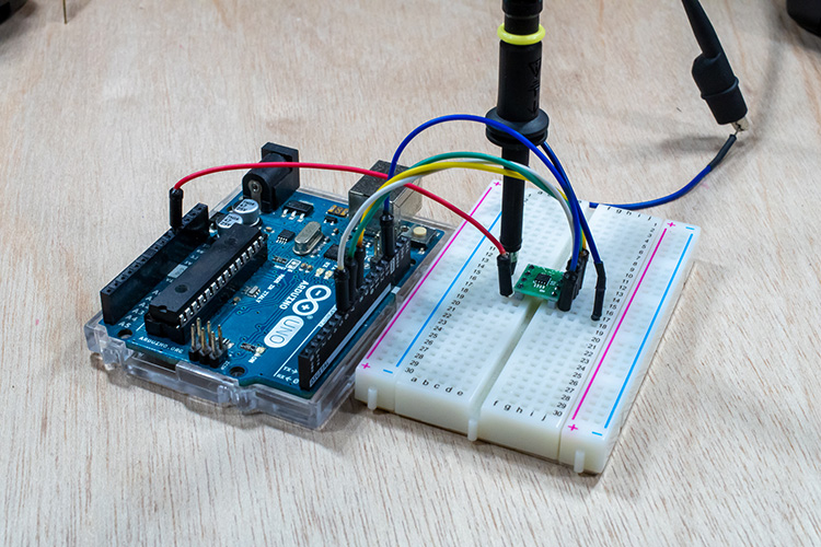
接下来,让我们在TFT显示屏上显示加速度计的数值!基本上,就传感器评估套件而言,我们无需更改TFT显示屏这边的连线。只需将KX022-1020加速度计插入传感器开发板即可。
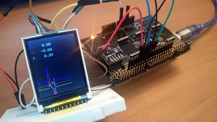
图3 加速度计和TFT显示屏
显示加速度计数值的程序如下:
#include <Wire.h>
#include <KX022.h>
#include <ST7735.h>
#include <SPI.h>
// You can use any (4 or) 5 pins
#define sclk 4
#define mosi 5
#define cs 6
#define dc 7
#define rst 8  // you can also connect this to the Arduino reset
// Color definitions
#define BLACK       	0x0000
#define BLUE        	0x001F
#define RED         	0xF800
#define GREEN       	0x07E0
#define CYAN        	0x07FF
#define MAGENTA     	0xF81F
#define YELLOW      	0xFFE0
#define WHITE       	0xFFFF
ST7735 tft = ST7735(cs, dc, mosi, sclk, rst);
KX022 kx022(KX022_DEVICE_ADDRESS_1E);
int _cnt = 0;
//Graph initial position
int _xc = 120;
int _yc = 130;
int _zc = 140;
void fillpixelbypixel(uint16_t color) {
for (uint8_t x=0; x < tft.width; x++) {
for (uint8_t y=0; y < tft.height; y++) {
tft.drawPixel(x, y, color);
}
}
delay(100);
}
void setup(void) {
byte rc;
Serial.begin(9600);
while (!Serial);
Wire.begin();
tft.initR(); // initialize a ST7735R chip
rc = kx022.init();
tft.fillScreen(BLACK);

1.DEVICE PLUS
testdrawtext("DEVICE PLUS!!", WHITE,25,50);
delay(1000);
tft.fillScreen(BLACK);
}
void loop() {
//KX022
byte rc;
float acc[3];
//2.Acquire accelerometer values
rc = kx022.get_val(acc);
if (rc == 0) {
Serial.write("KX022 (X) = ");
Serial.print(acc[0]);
Serial.println(" [g]");
Serial.write("KX022 (Y) = ");
Serial.print(acc[1]);
Serial.println(" [g]");
Serial.write("KX022 (Z) = ");
Serial.print(acc[2]);
Serial.println(" [g]");
Serial.println();
//Convert float type to char type
char xVal[10];
dtostrf(acc[0], 5, 2, xVal);
char yVal[10];
dtostrf(acc[1], 5, 2, yVal);
char zVal[10];
dtostrf(acc[2], 5, 2, zVal);
//Convert to TFT liquid crystal
//tft.fillScreen(BLACK);
tft.fillRect(0,0, 120, 60, BLACK);
testdrawtext("X:", RED, 5, 15);
testdrawtext(xVal, WHITE, 30, 15);
testdrawtext("Y:", BLUE, 5, 30);
testdrawtext(yVal, WHITE, 30, 30);
testdrawtext("Z:", GREEN, 5, 45);
testdrawtext(zVal, WHITE, 30, 45);
//3.Draw a graph
int x = int(acc[0]*100)+120;
int y = int(acc[1]*100)+130;
int z = int(acc[2]*100)+40;
tft.drawLine(_cnt-1, _xc, _cnt, x, RED);
tft.drawLine(_cnt-1, _yc, _cnt, y, BLUE);
tft.drawLine(_cnt-1, _zc, _cnt, z, GREEN);
_cnt++;
//Reset to the end of the screen
if(_cnt > 120){
_cnt = 0;
tft.fillScreen(BLACK);
}
_xc = x;
_yc = y;
_zc = z;

delay(10);
}
delay(10);
}
void testlines(uint16_t color) {
  tft.fillScreen(BLACK);
  for (uint16_t x=0; x < tft.width; x+=6) {
    tft.drawLine(0, 0, x, tft.height-1, color);
  }
  for (uint16_t y=0; y < tft.height; y+=6) {
    tft.drawLine(0, 0, tft.width-1, y, color);
  }

  tft.fillScreen(BLACK);
  for (uint16_t x=0; x < tft.width; x+=6) {
    tft.drawLine(tft.width-1, 0, x, tft.height-1, color);
  }
  for (uint16_t y=0; y < tft.height; y+=6) {
    tft.drawLine(tft.width-1, 0, 0, y, color);
  }

  tft.fillScreen(BLACK);
  for (uint16_t x=0; x < tft.width; x+=6) {
    tft.drawLine(0, tft.height-1, x, 0, color);
  }
  for (uint16_t y=0; y < tft.height; y+=6) {
    tft.drawLine(0, tft.height-1, tft.width-1, y, color);
  }
  tft.fillScreen(BLACK);
  for (uint16_t x=0; x < tft.width; x+=6) {
    tft.drawLine(tft.width-1, tft.height-1, x, 0, color);
  }
  for (uint16_t y=0; y < tft.height; y+=6) {
    tft.drawLine(tft.width-1, tft.height-1, 0, y, color);
  }
}
void testdrawtext(char *text, uint16_t color,int x,int y) {
 tft.drawString(x, y, text, color);
}
void testfastlines(uint16_t color1, uint16_t color2) {
  tft.fillScreen(BLACK);
  for (uint16_t y=0; y < tft.height; y+=5) {
    tft.drawHorizontalLine(0, y, tft.width, color1);
  }
  for (uint16_t x=0; x < tft.width; x+=5) {
    tft.drawVerticalLine(x, 0, tft.height, color2);
  }
}
void testdrawrects(uint16_t color) {
tft.fillScreen(BLACK);
for (uint16_t x=0; x < tft.width; x+=6) { tft.drawRect(tft.width/2 -x/2, tft.height/2 -x/2 , x, x, color); } } void testfillrects(uint16_t color1, uint16_t color2) { tft.fillScreen(BLACK); for (uint16_t x=tft.width-1; x > 6; x-=6) {
  tft.fillRect(tft.width/2 -x/2, tft.height/2 -x/2 , x, x, color1);
  tft.drawRect(tft.width/2 -x/2, tft.height/2 -x/2 , x, x, color2);
}
}
void testfillcircles(uint8_t radius, uint16_t color) {
 for (uint8_t x=radius; x < tft.width; x+=radius*2) {
   for (uint8_t y=radius; y < tft.height; y+=radius*2) {
     tft.fillCircle(x, y, radius, color);
   }
 }
}
void testdrawcircles(uint8_t radius, uint16_t color) {
 for (uint8_t x=0; x < tft.width+radius; x+=radius*2) {
   for (uint8_t y=0; y < tft.height+radius; y+=radius*2) {
     tft.drawCircle(x, y, radius, color);
   }
 }
}
运行上述程序后,显示屏会将加速度计的数值用图形显示出来。
该程序流程摘要如下:
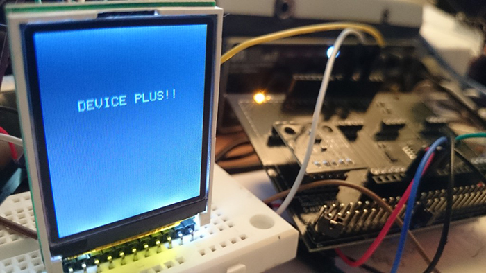
- 启动时显示 “DEVICE PLUS !!” 字符
- 获取加速度计的数值并将其转换为整数
- 根据数值显示图形和文本
每一帧我们给x轴加1,以便从左到右绘制图形。
当画面到达120px显示屏的边缘时,程序会用drawrect清除图形。屏幕上方的数字以相同的方式通过drawrect进行每帧更新。
至此,利用TFT液晶显示屏显示加速度计的数值并绘制相关图形的教程就结束了!我们还可以考虑开发更多的附带项目。比如,我们可以将此TFT显示屏与Arduino Pro Mini组合在一起,制作具有小型游戏功能的手表等;还可以利用传感器评估套件中的不同传感器来制作数据记录器。
DevicePlus 编辑团队
设备升级版适用于所有热爱电子和机电一体化的人。